This example features Keithley 2401 SMU (source measure unit) that is used to measure circuit resistance using dynamic current levels.
This method utilizes the GPIB Freestyle node (.GF) that allows the use of any type GPIB instrument within the Omega software, and the dynamic expression injection ($GPIB1) into the used GPIB code.
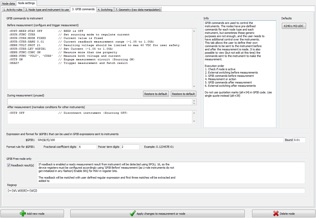
Since the instrument is used through .GF node, and therefore the instrument is not initialized, it must be configured in the 'GPIB to instrument before measurement' section. For example, the instrument is instructed not to make beeping sound each time a circuit is engaged.
The exiting part is where instead of using a static current level, we tell to set the current level to $GPIB1, which in turn is a value resulting from evaluation of the $GPIB1 expression each iteration/execution of this node. In this example we are taking a sine wave of $I/5 where the $I is the index number, or the running count, of the amount of executions the node have had. The result is divided by 100, so we have a sine wave normalized between -0.01 and 0.01 amps. The 'Bound' is a safety limit in case the (more complex) expression had errors or unforeseen features, and would result for example a value of 1000, potentially unsafe value (for the sample or the user). Bound 0.01 limits the result of the expression to minimum -0.01 and maximum 0.01.
The format is a rule that defines how the resulting number is represented as text before sent to the instrument. A number is amount of 0 and 1 in the memory of the computer, then turned into a text, sent to the instrument each of which have their own rules how to turn text back into binary data. Too many or few numbers and the instrument will misinterpret or even crash. Correct number format is usually (but not always) mentioned in the instrument manual.
In our case the Keithley 2401 SMU uses + or minus then a digit from 0 to 9 then a dot then one to six digits then small or capital e then plus or minus and then two digits, where plus signs can be omitted and dot must be omitted if no digits follow. This format is automatically created and the user only has to define how many digits after the dot and how many numbers on the exponent. If the instrument uses some other form of notation for it's number that is not possible to express with Omega, take contact and we will add suitable formatting options.
In this case we are reading back a result, and likewise we need to interpret the text retrieved from the instrument. In this case the result is a text string something like +1.000206E+00, +1.000000E-04, +1.000236E+04, +7.282600E+01, +4.813200E+04 and the software is using regexp (regular expression) to pick possible numbers from that string. These expressions can be confusing, but they are an exact way to define the rules (such as mentioned in above paragraph) in a compact form. We are happy to provide the correct regular expression to the user if they send us a request and the instrument manual on email. Then it is just a matter of copy-pasting the correct text into the 'Regexp'-field.
By using 'output off' command after the measurement, it is ensured no current is sent through the sample unnecessarily. Also note that the sin function changes current polarity periodically, which may be useful for various reasons. For example to ensure the measurement does not change the net reactions in the sample, or to eliminate the effect of thermal offset voltages on the calculated resistance. (Reverse and average will get rid of the error caused by thermal offset voltages).
It may be desirable to add #SLEEP 500 between the :OUTP ON and the :READ? lines, to make the software wait 500 milliseconds before the measurement is taken, to properly soak the sample with current. Most instruments make many quick measurements and only return result when the read values have stabilized, but this is not the case with all instruments, or all operation modes. The half second wait will ensure better quality (more accurate considering equilibrium) data. When the quick changes are of interes, perhaps some other quicker-performing approach is better suited.
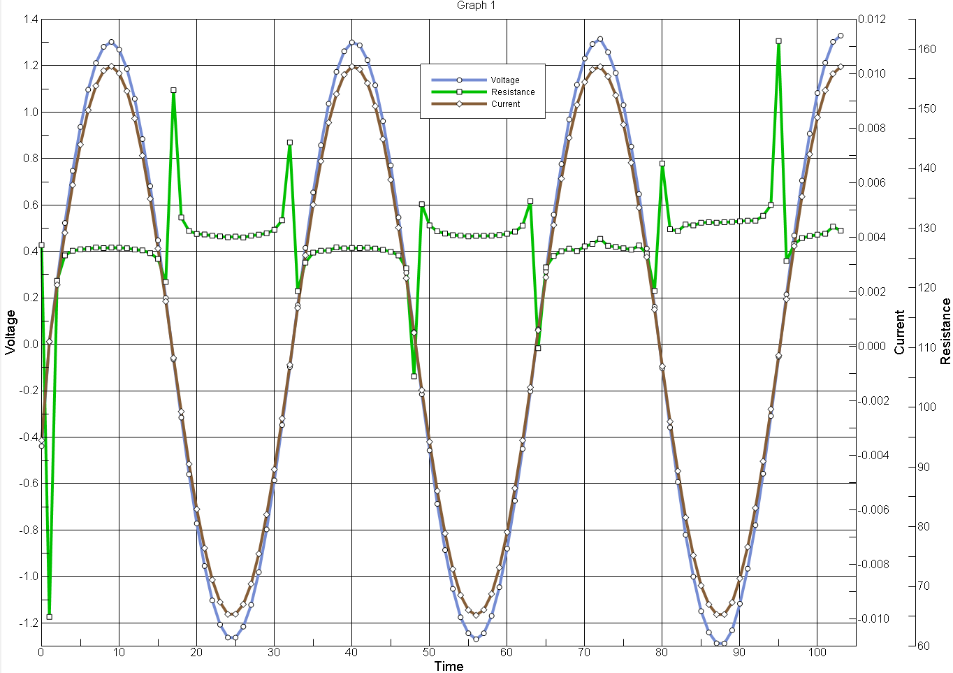
When the data is plotted with $N1.DF1 and $N1.DF2 (Node 1, data field 1 and data field 2 accordingly) we get the measured voltage and current plotted as seen below. Resistance is also calculated ($N1.DF1/$N1.DF2) from these values.
The sample is two resistors laying on table held together loosely by alligator clips, so the contact is bad and the table is shaking, causing artifacts to the data, so the plots do not represent the instrument performance. In fact, K2401 is extremely precise and accurate.